5.6 The Fixture Library Editor
This section explains the Library Editor which is used throughout the library creation or edit process.
The Library Editor consists of three different pages, which we will explain in this section: Fixture Type, Modules and Instances.
The Modules tab will always be displayed first. To switch to the other pages, select the desired tab on the top of the dialog.
5.6.1 General information about fixture types and terminology
Fixture types are structured using modules and instances to define their functionality.
- Modules: A module represents a template for how DMX channels are mapped to the functions of a fixture, such as controlling color, intensity, or movement. Each module is specific to a fixture type and contains a defined number of channels. A fixture must include at least one module with at least one channel, but it can contain multiple modules to represent different functional groups within the fixture.
- Instances: Instances use the modules to define specific parts of the fixture. Each instance references a module and specifies its user number, name, and DMX start address within the fixture. Fixtures must include at least one instance, but they can have many, depending on the design. Instances may overlap within the fixture as long as their functions do not conflict.
Imagine a fixture like an LED bar with 10 individually addressable LEDs. Each LED uses the same functionality—color control through three DMX channels (Red, Green, and Blue). Instead of creating a separate module for each LED, you would define a single module for one "pixel" (three channels: RGB). Then, you would create 10 instances of this module, assigning each instance a unique user number and mapping it to the correct DMX start address. This approach simplifies configuration and avoids redundant setup.
In this way, modules and instances provide a powerful and efficient method to organize and control complex fixtures while minimizing repetitive work.
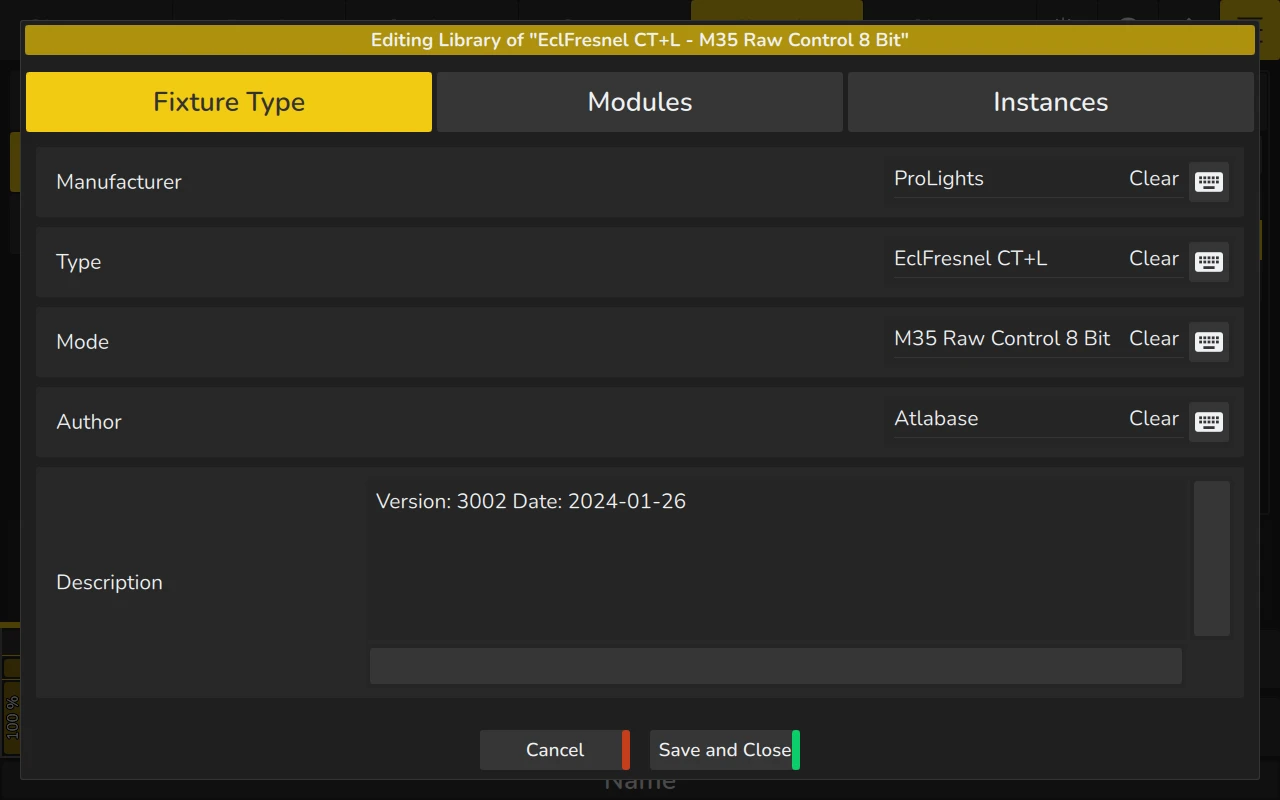
5.6.2 Fixture Type Tab
The Fixture Type tab contains text fields to enter the fixture Manufacturer, Type (Fixture Name), Mode, Author, and a description.
The Manufacturer, Type and Mode cannot be changed if the fixture is inside the Show Library!
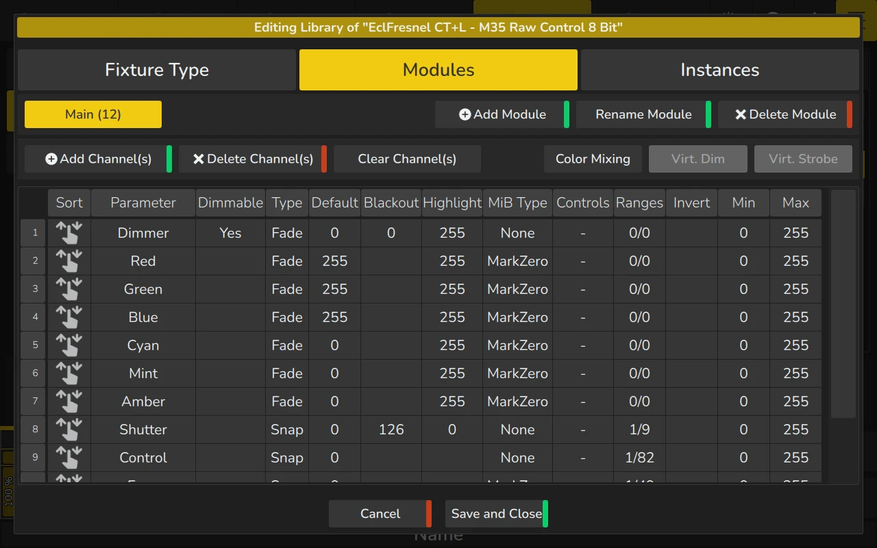
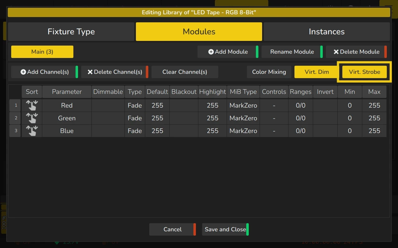
5.6.3 Modules Tab
The Modules Tab serves as the module editor for defining how DMX channels map to the fixture's functions. The interface provides tools to create, rename, and delete modules, as well as configure individual channel properties.
-
First Toolbar Row:
- Module List: Displays a button for each module in the fixture..
- Add Module: Creates a new module for the fixture.
- Rename Module: Renames the selected module.
- Delete Module: Removes the selected module entirely.
-
Second Toolbar Row:
- Add Channel(s): Appends new channels to the end of the module.
- Delete Channel(s): Deletes selected channels from the module.
- Clear Channel(s): Resets the mapping of the selected channels while keeping them in the module.
- Color Mixing (RGBxxxx): If the fixture supports RGB color attributes, this button allows quick setup for Red, Green, and Blue channels, along with additional colors like Amber or White.
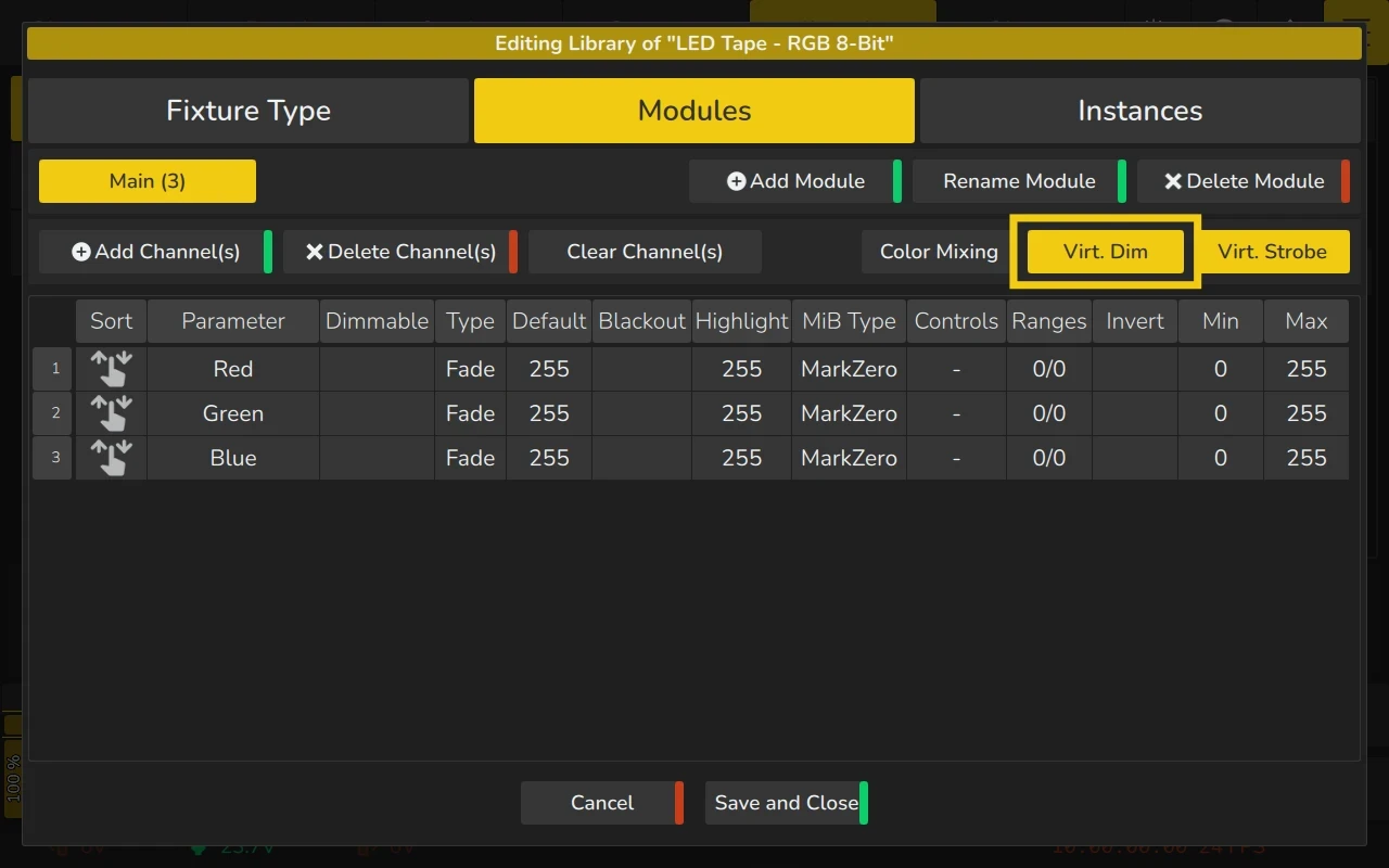
- Virtual Dimmer: Adds a virtual dimmer function to control overall brightness. This option requires the fixture to include RGB (or similar) channels but no physical dimmer channel.
- Virtual Strobe: Adds a virtual strobe function to the fixture. This feature requires the fixture to have either a physical dimmer channel or a virtual dimmer set up beforehand.
The channel list allows you to configure the behavior of each channel. Each row corresponds to a channel, which is appended to the end when added.

Adding a Module
To add a new module, click the Add Module button within the Modules tab. In the dialog that appears, enter the module's name and specify the number of channels (representing the individual part of the fixture). You can also add a description if desired. Channels can be added or removed later on.
For example, if you're creating a module for RGB pixels, the channel count would typically be 3 channels.
Once you've entered the details, you have two options:
- Click Add and Add More to continue adding additional modules to the fixture type.
- Click Add and Edit Module to add the module and immediately begin editing its channels.
Rename a Module
To edit a module's name, select it from the list and click the Rename Module button within the Modules tab.
Delete a Module
To delete a module, select it from the list and click the Delete Module button within the Modules tab.
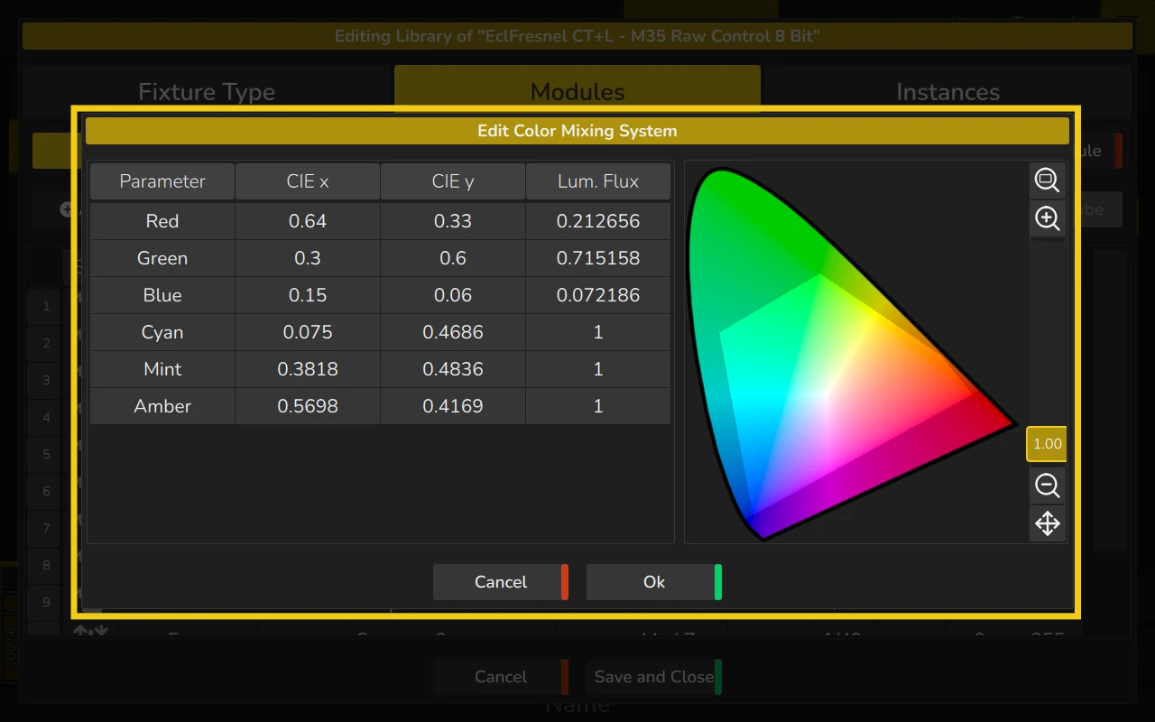
Defining the fixtures Color Space for the color pickers
The Color Mixing button will appear within the Modules Tab if the fixture uses an additive color mixing system. Clicking on this button opens the Edit Color Mixing System dialog, where you can define or modify color spaces for the fixture.
In the dialog, you can double-tap each cell to adjust the coordinates for CIE x, CIE y, and Luminous Flux for each emitter. The Luminous Flux can be provided in any units, as long as the units are consistent across all channels.
To return to the conventional fixture color management, set the luminosity of all emitters to 1, equalizing their output. This will seamlessly transition to the default configuration, which is used for fixtures without specific light source data in the library. This same approach is recommended for fixtures operating in factory-calibrated mode.
On the right side of the Edit Color Mixing System dialog, you can preview the color space defined by the provided coordinates.
Adding a Virtual Dimmer
By enabling the virtual dimmer, you may add dimmer functionality to the fixtures that do not have a dedicated dimmer function but use a color mixing system (RGBxxxx, CMY, HSI or CIE).
To do so, click on the Virtual Dimmer button from within the Modules tab.
Adding a Virtual Strobe
Fixtures equipped with a single dimmer channel (whether virtual or non-virtual) but lacking a shutter channel can use a Virtual Strobe function. To enable this, click the Virtual Strobe button within the Modules Tab.
The Channel / Function List
Within the Modules Tab, you'll find a table used to alter the mapping of DMX channels to attributes. This table is called the Channel List.

To edit a value, select the cell you wish to change and double-tap or long-press it.
| Column | Function |
|---|---|
| Vertical Header | Displays the DMX channel number, which cannot be changed. You can add or remove channels using the Add Channel(s) or Delete Channel(s) buttons in the toolbar. |
| Sort | Allows you to rearrange the channel layout, such as moving channel 1 to channel 6 without losing any settings. |
| Parameter | Defines the function of this channel. See the "Edit Parameter" section for more details. |
| Dimmable | Defines if this channel should react to Dimmer Faders or the Grand Master fader. |
| Type | Determines how the channel changes values: Fade means a smooth transition, while Snap means an instant change. This is useful for functions like Color or Gobo Wheels. |
| Default | Specifies the value output when the Grand Master fader is at 0% or when blackout is activated. |
| Blackout | Defines the value that will be output for the channel when the Grand Master fader is at 0 percent or when blackout is active. |
| Highlight | Defines the output value when the “Highlight” function is active in the programmer, typically 100% brightness and white. |
| MiB Type | Specifies the behavior of the channel with Move in Black functionality: None: The channel will not pre-position. Mark: The channel fades to the new value. MarkZero: The channel snaps to the new value. |
| Controls | Defines the controlling functions of this channel’s range sets. |
| Ranges | Maps DMX values to text labels, icons, colors, or real-world values (e.g., for pan and tilt). The range names are shown in the programmer and the "Select Range" popup when using an encoder or its label. Range sets are activated by controlling functions. When one or multiple controlling functions are set for this channel, Range Sets can be created. Each Range Set may contain different ranges and is activated based on values of the controlling function. More info and an example for range sets can be found in the “Edit Ranges” section below. |
| Inverted | Inverts the DMX output for this channel. For example, a value of 100 in the programmer will output as 156. Default, Highlight, and Blackout values must still be entered as non-inverted values. |
| DMX Min | Sets a hard limit for the minimum value of this DMX channel. |
| DMX Max | Sets a hard limit for the maximum value of this DMX channel. |
Edit Parameter Dialog
The Edit Parameter dialog allows you to select the parameter assigned to a channel. This can be accessed by double-clicking or long-pressing a parameter cell within the channel list.
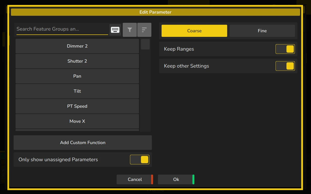
A list of available functions is displayed on the left-hand side of the Edit Parameter dialog. You can filter this list by entering text into the Filter Text field at the top of the screen. Additionally, you can choose to display only unassigned parameters by toggling the "Show Unassigned" option. If this option is off, you will see all parameters, including those already assigned in the channel list.
Each function in this list can only be assigned once within a module.
The Coarse and Fine buttons allow you to toggle between assigning a coarse or fine channel.
When changing an existing parameter to a new one, you can choose to keep or remove the current ranges by using the Keep Ranges toggle button.
The Keep Other Settings toggle button allows you to retain or reset the settings for Dimmable, Type, Default, Blackout, Highlight, MiB Type, Inverted, DMX Max, and DMX Min when changing a channel's parameter.
You can add custom functions with unique names by clicking on Add Custom Function. These will be placed in the Special feature group, but can be moved to different feature- or sub-groups using the Encoder Editor, which is explained in the corresponding section 5.2.8 Encoder Editor.
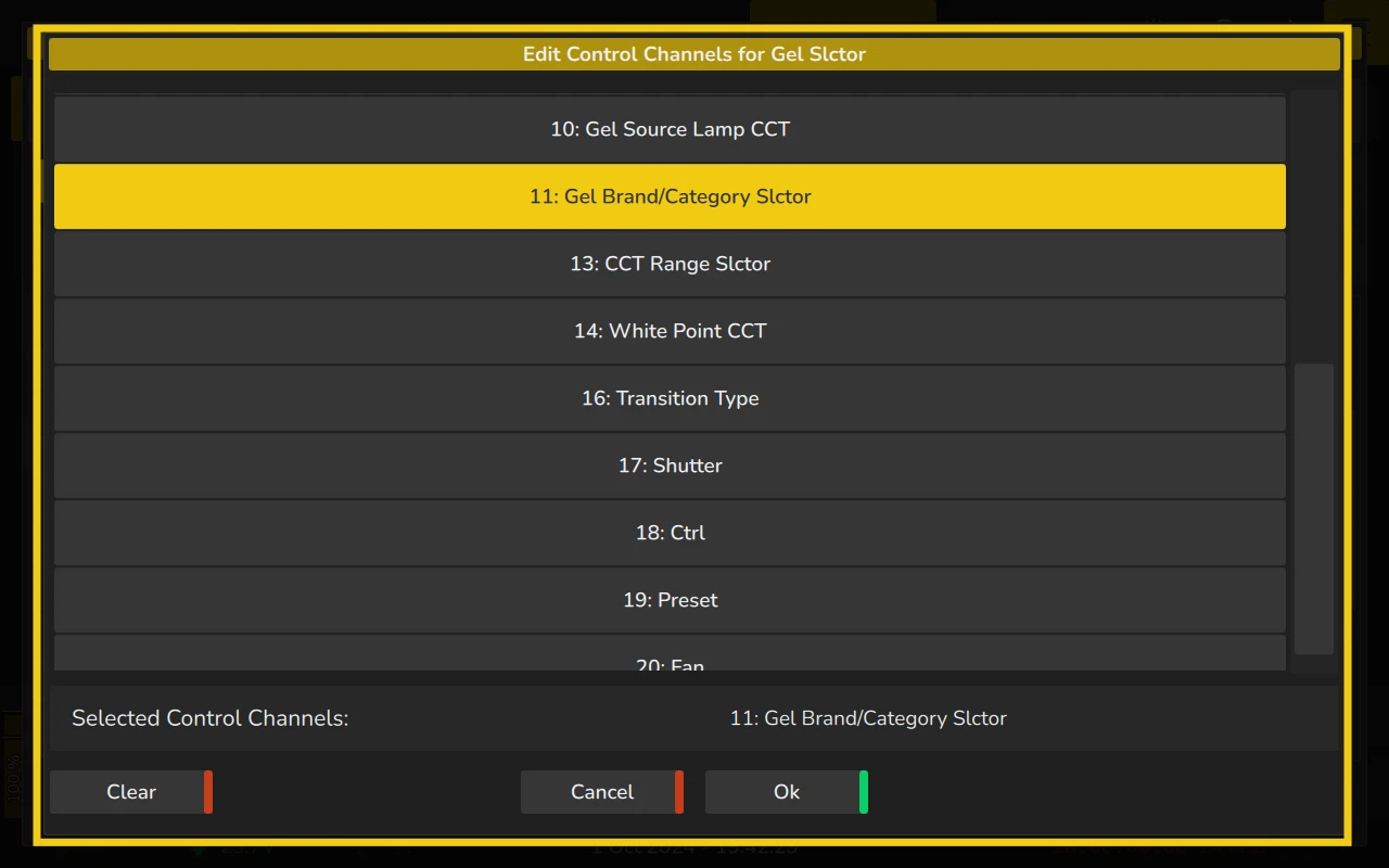
Edit Control Functions
This dialog allows you to assign controlling functions to the current function’s range sets. A controlling function is a parameter whose value determines how the ranges of the current function are displayed.
For example, consider a Gobo Function and a Gobo Rotation Function. The Gobo Function might include options such as "Indexing Gobo" and "Rotating Gobo." When "Indexing Gobo" is selected, the Gobo Rotation Function displays values in degrees. Conversely, when "Rotating Gobo" is selected, the Gobo Rotation Function displays rotational speeds in RPM.
To assign a controlling function, you can select the desired functions from the list provided in the dialog. These functions represent all available options within the selected modules that can influence the current function’s behavior.
Once the desired controlling functions are selected, click OK to confirm and apply the changes.
if you wish to remove all assigned controlling functions, simply click the Clear button.
Using multiple controlling functions allows you to fine-tune the behavior of the channel's range sets. Each controlling function will dynamically impact the displayed ranges based on its current value. For more information about Range Sets, please see Adding or Editing a Range Set.
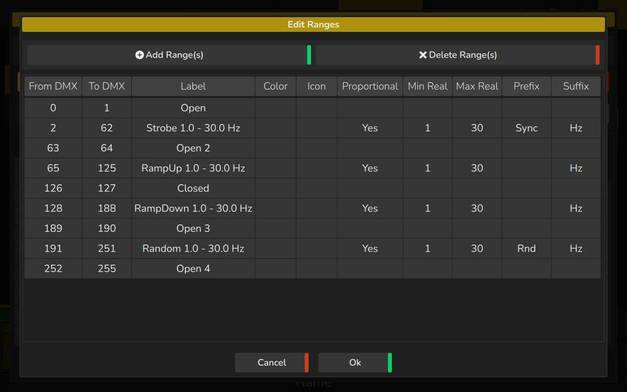
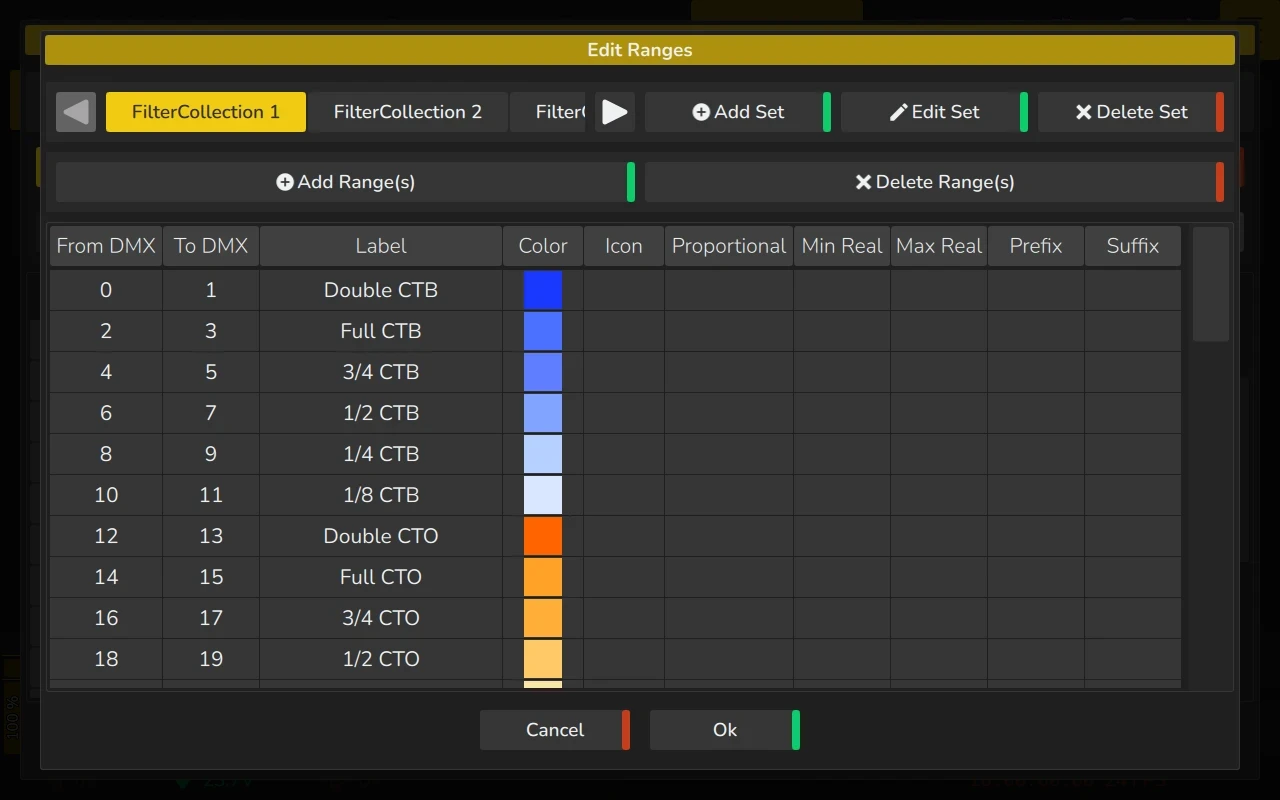
Edit Ranges Dialog
The Edit Ranges Dialog allows you to map DMX values of a channel or function to user-friendly textual descriptions. This feature enables the display of names or even icons for specific ranges of values in the programmer, on encoder labels, and in the set value popup that appears when you press an encoder.
To open the dialog, simply double-click or long-press the Ranges cell for the relevant parameter in the channel list.
The Edit Ranges Dialog displays a table with several columns, where you can edit the values by double-clicking or long-pressing the respective cells:
- From DMX: Defines the starting value of a range.
- To DMX: Defines the ending value of a range.
- Label: The text label shown in the encoder label, values table, and set value dialog (which appears when an encoder is pressed). If a range is set to Proportional, the encoder label and values table will display the prefix, the calculated value based on Min Real and Max Real, as well as the suffix, while the set value dialog will display the label.
- Color: Allows you to assign a color to the range, which will be displayed as an icon in the values table, fixture items, and set value dialog.
- Icon: Lets you select an icon for the range, which will appear as an icon in the values table, fixture items, and set value dialog.
- Proportional: Determines if the range is proportional. The value displayed will be calculated based on the relationship between the Min Real and Max Real values and the From DMX and To DMX values.
- Min Real: Defines the real-world value that corresponds to the From DMX value.
- Max Real: Defines the real-world value that corresponds to the To DMX value.
- Prefix: Specifies the text displayed before the value if the range is proportional.
- Suffix: Specifies the text displayed after the value if the range is proportional.
If the function has any controlling functions set, the Edit Ranges Dialog will also feature a toolbar similar to the one in the Modules Editor. This toolbar displays a list of all range sets. From here, you can add, edit, or remove range sets as needed.
A range set is a way to define specific behaviors or states of a fixture function based on input values, typically DMX values. These sets allow you to map ranges of values to particular actions, effects, or attributes of a fixture depending on another functions value.
When no controlling functions are set, the function only contains one range set which is always active.
Adding or Editing a Range Set
When controlling functions are introduced, a range set becomes conditional, meaning that the active range set for a particular function depends on the value of the controlling function(s). This is useful for situations where the behavior of one function (e.g., Gobo Rotation) depends on another function's state (e.g., Gobo Type being "Indexing Gobo" or "Rotating Gobo").
By defining range sets and linking them to controlling functions, the lighting console ensures that the correct ranges are applied dynamically based on the overall configuration, allowing for more intuitive and flexible programming. This is especially helpful in managing complex fixtures with many interdependent features.
If a function has controlling functions assigned, the Edit Ranges Dialog will include a toolbar similar to the one found in the Modules Editor. This toolbar provides an overview of all range sets and offers tools to add, edit, or remove range sets as necessary.
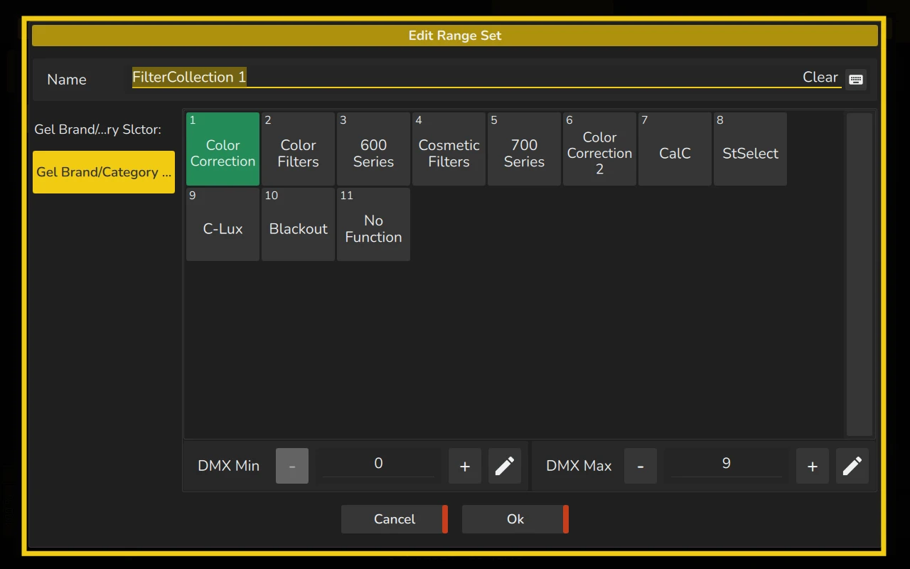
To add a new range set, click on the Add Set button. This action opens the Edit Range Set Dialog, where you can configure the details of the new range set. Similarly, to modify an existing range set, select it and click on the Edit Set button. This opens the same Edit Range Set Dialog, allowing you to update its properties.
Within the Edit Range Set Dialog, you can assign a name to the range set, making it easier to identify in the future. On the left-hand side of the dialog, you will find a list of the controlling functions. Selecting a controlling function from this list displays its ranges on the right-hand side.
The right-hand side is where you define the range of values for the controlling function that will activate the range set within the selected function. If multiple controlling functions are assigned to a function, you must specify a range of DMX values for each controlling channel. These ranges collectively determine when the range set will be activated.
Adding Ranges
The Add Range(s) Dialog provides several options for adding one or multiple ranges to a range set. On the right side of the dialog, you will see a preview of the ranges that will be created based on your selections
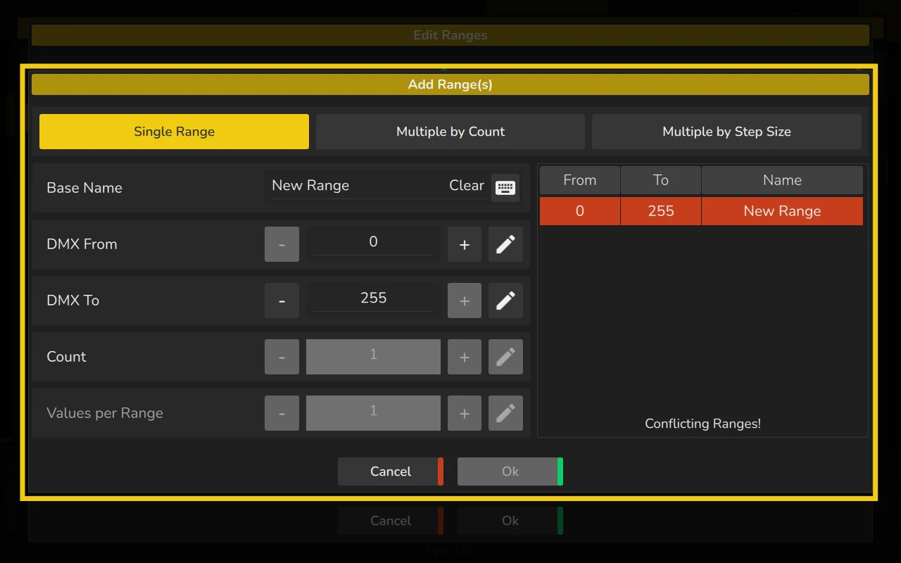
To add one or multiple ranges to a Range Set, follow these steps:
- Click the Add Range(s) button within the Edit Ranges Dialog.
- Choose the type of range you want to add: Single Range, Multiple by Count, or Multiple by Step Size.
- Enter the base name for the new range(s) in the text field.
Then, proceed with one of the following methods:
-
Single Range
- Define the start value in the DMX From spin box.
- Define the last value of the range in the DMX To spin box.
- Click Ok.
-
Multiple by Count
- Define the start value in the DMX From spin box.
- Define the last value of the range in the DMX To spin box.
- Specify the number of ranges to be created using the Count spin box. The resulting ranges will be evenly distributed across the DMX From to DMX To values.
- Click Ok.
-
Multiple by Step Size
- Define the start value in the DMX From spin box.
- Specify the number of ranges to be created using the Count spin box.
- Enter the number of values per range in the Values per Range spin box.
- Click Ok.
Editing Ranges
To edit an existing range, double-click or long-press on the corresponding entry in the table. This will allow you to modify the range settings directly within the table. You can adjust the values, labels, colors, icons, and other parameters as needed.
You can mix both Non-Proportional and Proportional ranges within the same function or range set.
- Non-Proportional Ranges are typically used when the DMX values correspond directly to specific steps or functions, such as a simple on/off or specific color on a color wheel..
- Proportional Ranges, as explained below, allow the DMX values to be proportionally mapped to real-world values, such as speed, frequency, or other continuous functions.
By combining both types, you can provide a more flexible and precise mapping for various lighting functions, making it easier to control both discrete and proportional attributes within the same fixture or channel. This setup enables more complex and versatile control over the fixture’s behavior, especially when the function has both discrete steps and continuous ranges.
Non-Proportional Range
A range which indicates a certain function on a channel.
A Non-Proportional Range defines a set of values where each DMX value or a small subset of DMX values directly corresponds to a specific function or state.
For example, in a Gobo Wheel function, each DMX value might represent a discrete gobo. Here, there’s no interpolation or proportional scaling between the DMX values; each value or range of values triggers a specific, predefined result.
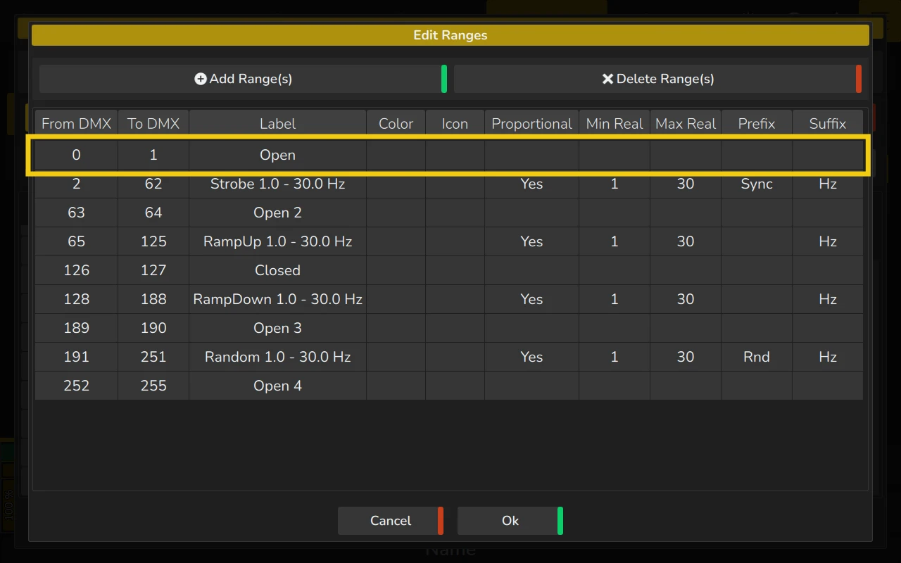
Proportional Range
A range which indicates a certain function that has a range of values (such as pan tilt or strobe) on a channel.
By double tapping on the Proportional cell, in the Edit Ranges dialog, you will be able to set it to Yes.
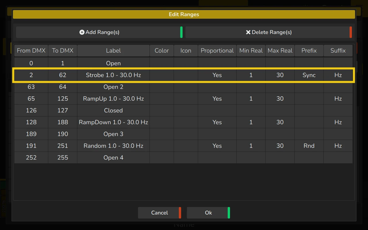
On the right side of the screenshot, next to Proportional, Min Real and Max Real, Prefix and Suffix cells are shown.
The Min Real and Max Real equal the read-out in the programmer or output table for the Min and Max DMX Value respectively. When the channel is at value 16, the readout will be 1, when the channel is at 255 (100%), then the readout will be 10. Any other values in between would be calculated accordingly.
The Prefix is shown before the actual value, the Suffix is shown after the value. For example, in a strobe channel the prefix could indicate the type of strobe (usually Sync or Rnd) whereas the suffix indicates “Hz” for the frequency.
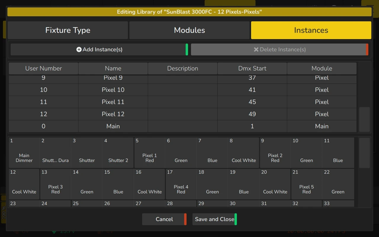
5.6.4 Instances Tab
The Instances Tab allows you to manage and edit the instances associated with the fixture. At the top of the tab, a toolbar contains buttons to add or delete instances:
- Add Instance(s): Click this button to add one or more instances.
- Delete Instance(s): To delete one or more instances, select them from the list and click this button.
The central part of the tab displays a table with the following columns:
- Instance User Number: The part on the right side of the fixture number (e.g., the "1" in "Fixture 1.1").
- Name: The name assigned to the instance.
- Description: A description for the instance.
- DMX Start: The DMX start address for this instance, relative to the entire fixture.
- Module: The module referenced by this instance.
To edit any of these attributes, simply double-click or long-press the corresponding cell in the table. This allows you to modify the Instance User Number, Name, Description, DMX Start, and Module.
At the bottom of the dialog, a preview of the full fixture is shown, displaying the channel numbers and function names. This helps you visually confirm the layout and structure of the fixture setup.
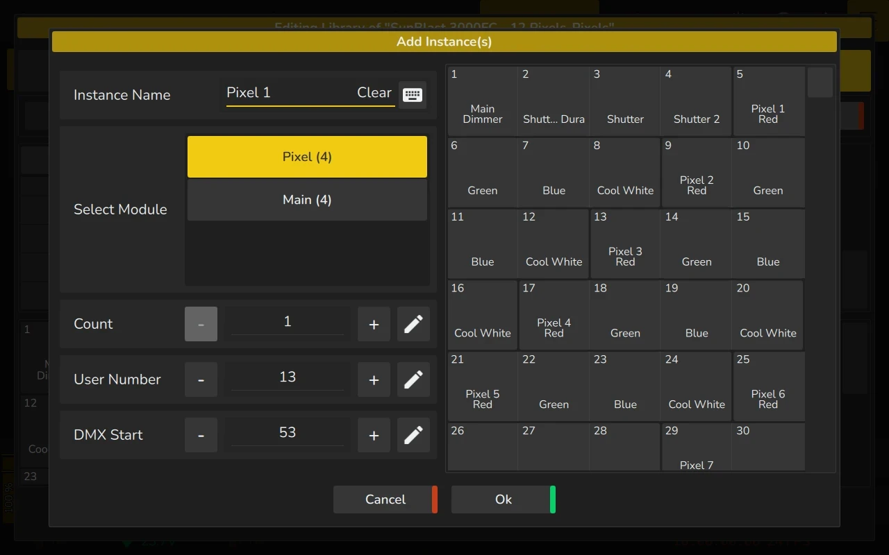
Adding Instances
To add an instance of a module to the fixture type, click on the Add Instance button. This will open a dialog where you can configure the instance settings.
In the dialog, you can:
- Name: Enter a name for the instance.
- Select Module: Choose which module you want to use for this instance from the drop-down list.
- Count: Set the number of instances you wish to add. This allows you to add multiple instances at once.
- User Number: Specify the user number, which appears on the right side of the fixture number (e.g., in "Fixture 2.1," the "1" is the user number).
- DMX Start: Define the DMX start address for this instance, indicating where it will begin in the fixture's DMX map.
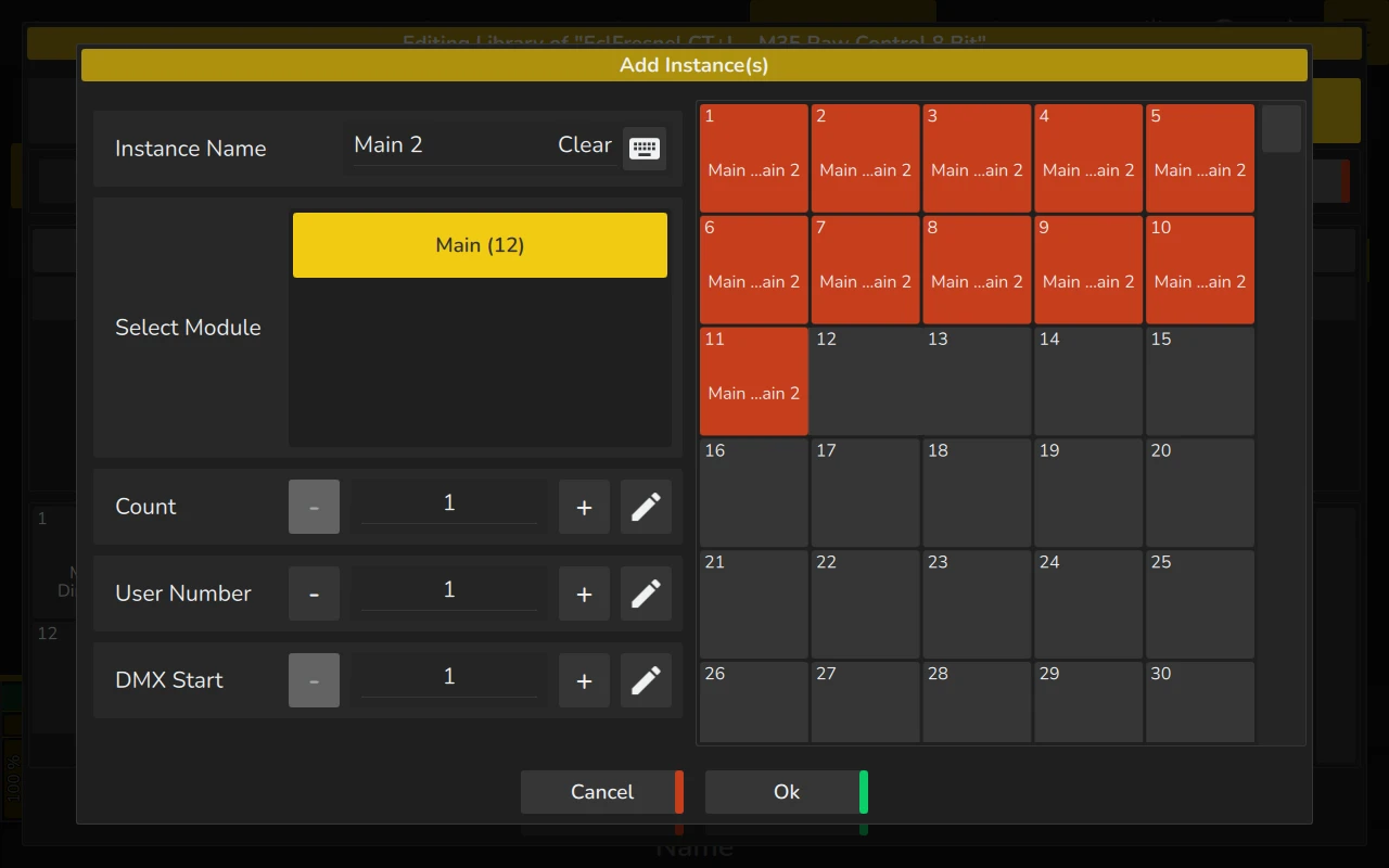
On the right side of the dialog, a preview of the full fixture is displayed. You can select the DMX Start directly in the preview by tapping on the desired DMX location. If there is a conflict with the selected DMX channel (e.g., if it overlaps with an already assigned channel), the conflicting channels will be highlighted in red to help you avoid conflicts.
Once you have entered all the necessary information and confirmed that there are no DMX conflicts, click Ok to add the instance. All instances will be added in consecutive order based on the DMX start value.
Deleting Instances
To delete an instance, simply select it from the list of instances and click on Delete Instance. A confirmation dialog will be shown.